
Most big brake kits ship with a bag of shims. That bag is an admission: the bracket does not quite line up with the caliper, so the installer is asked to make up the difference.
Shims work, but they add a stack of tolerances at the one joint where you least want play. We attack the problem upstream instead — measuring the actual vehicle, then machining brackets and rotors in a single setup so the designed geometry survives into the finished part.
The three stages
3D scanning
Every application starts with a 3D scan of the actual vehicle hub, upright, and wheel. Not a drawing, not a published dimension — the part as it left the factory. That lets us work from real-world installation geometry rather than relying solely on nominal dimensions, and gives us an accurate digital reference for the critical mounting points, clearances, and component relationships on the vehicle being developed.
3D design and clearance testing
The bracket and rotor are designed against that scan, then exercised digitally. Suspension travel, steering lock, and wheel clearance are checked through their full range before anything is cut, so interference is caught in software rather than in a customer's wheel well.
5-axis machining
The parts are cut on 5-axis machines in a single setup. Holding the part once, rather than re-fixturing between operations, minimizes re-fixturing error and helps maintain the designed geometric relationship between critical mounting surfaces. That is what allows the caliper, bracket, and rotor assembly to achieve precise alignment without relying on corrective installation shims.
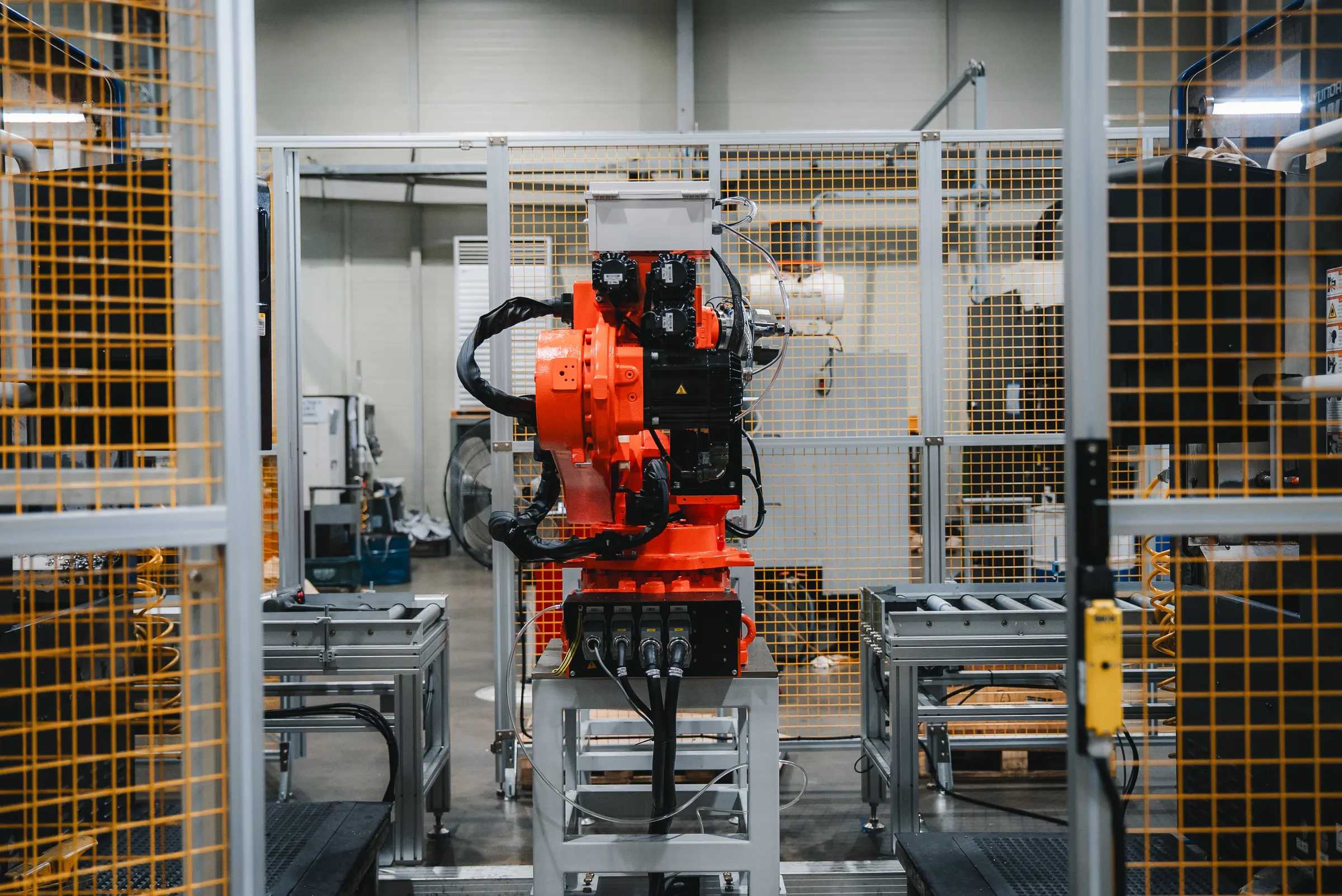
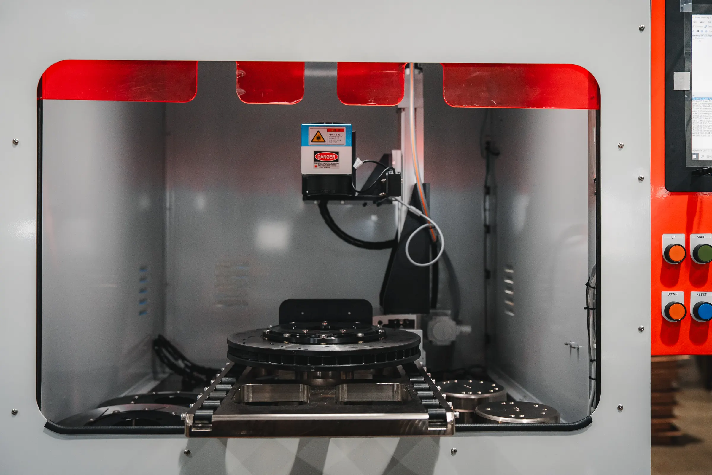
What we hold, and why it matters
| Measure | Tolerance | What it prevents |
|---|---|---|
| Weight balance | Under 10 g | High-speed vibration; uneven suspension wear |
| Disc thickness variation (DTV) | Under 0.02 mm | Brake judder; uneven pad wear |
| Runout | Under 0.03 mm | Pedal pulsation; inconsistent pedal feel |
Weight balance under 10 grams. An unbalanced rotor is a rotating mass with a bias, and at speed that bias becomes vibration you feel through the steering wheel. Holding imbalance under 10 g keeps the assembly quiet at track speed and reduces the load cycling into suspension components on the road.
DTV under 0.02 mm. Disc thickness variation is the difference between the thickest and thinnest points around the friction ring. When it grows, the pad is alternately squeezed and released once per revolution — that is brake judder. Keeping it under 0.02 mm gives uniform pad contact and even wear.
Runout under 0.03 mm. Runout is lateral deviation as the disc rotates. Excess runout is the usual seed of DTV: the disc wipes the pad on one side each revolution, wearing itself unevenly until judder appears months later. Controlling runout at manufacture is what keeps the other two numbers stable over the life of the disc.